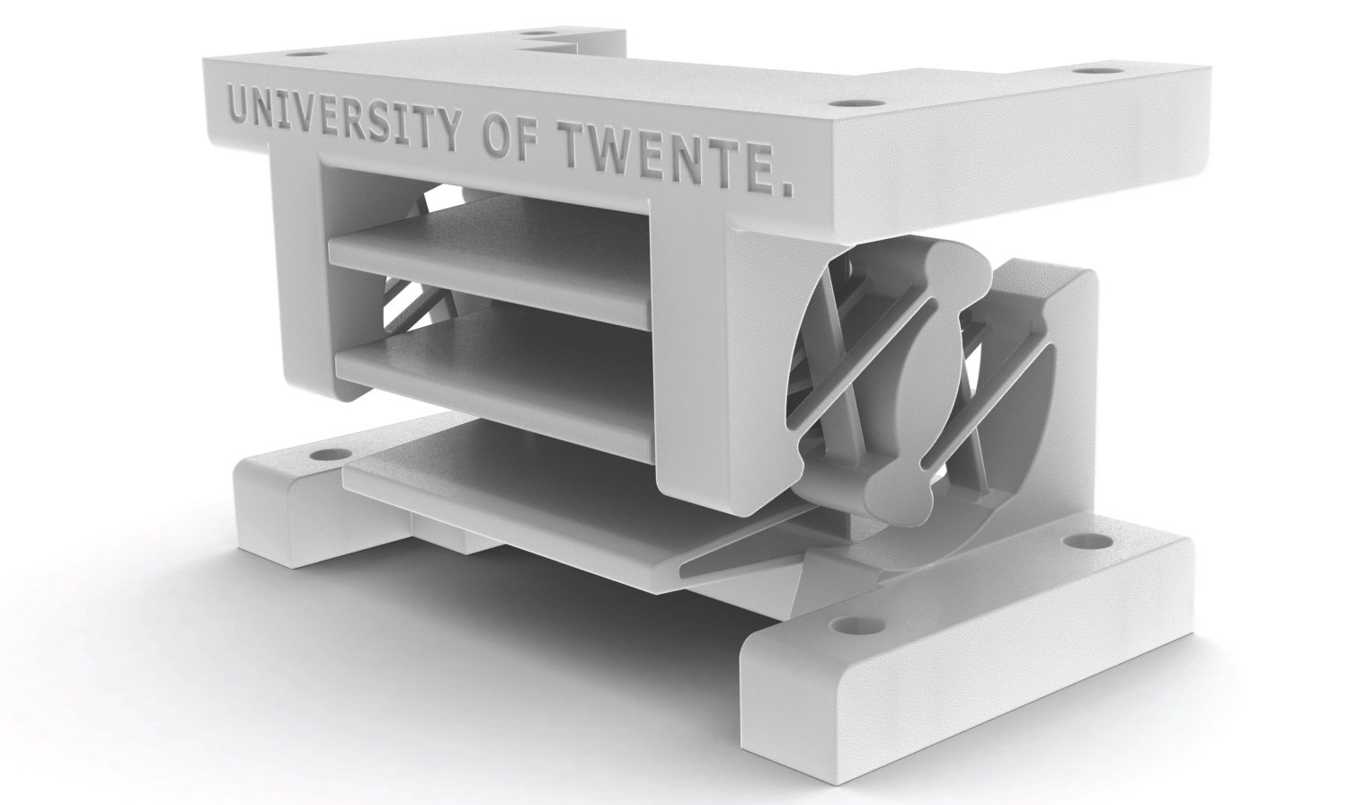

motions that only involve pure translations and rotations. The concepts generated from CBD are therefore limited by the building blocks that possess simple motions, i.e. An example of a CBD building block is flexural beams with intersecting lines of action form an instant center about which a stage may rotate. There is a nice list in the back of the book "The Handbook of Compliant Mechanisms." Also, there is a way to transform linkages into flexures: the pseudo-rigid body model (PRBM) developed by Larry Howell.Ĭonstraint-based design generates compliant mechanisms via flexural building blocks. There have been several flexure designs that have been developed already. See chapter 1 of my Master's thesis for more information on these techniques. There are several methods, including using an old solution, constraint-based design, topological synthesis, Freedom, Actuation, and Constraint Topologies (FACT), and Transmission Theory (a major contribution from my Master's thesis.) FACT is an intuitive and powerful tool for flexure design. These specifications will aid the choice in flexure topology.įlexure concepts can be generated once the kinematics have been identified. That is, the required ranges of motion in the degrees of freedom and constraint should be specified. Once the degrees of freedom are identified, they should be characterized. Keep in mind that the flexures that you design will not be infinitely stiff in the constraint directions, but if designed properly will be orders of magnitude stiffer than the degrees of freedom. Every rigid body has six degrees of freedom: three for translation and three for rotation. That is, it may be easiest to identify which directions are undesirable for travel. Conversely, you could find the desired constraints first. These are the desired directions of travel. The first step in flexure design is to identify the degrees of freedom. Flexures are typically modeled using FEA, which is the subject of another entry. That way, you can change one variable at a time and see how that affects the entire system. Once the equations are developed, you should put these variables in a MATLAB script or an Excel spreadsheet. How short can I make this beam so that it can be at 30% of the yield stress? The model should answer questions like that, keeping real-world constraints in mind.īy carefully applying these equations to your system, you should have a decent approximation for its behavior. In other words, the model shows you which direction to go and by how much. There should be a pencil-and-paper approximation that allows you to see which variables are most important and it gets you in the ballpark of the correct dimensions. The functional requirements for flexures include (but are not limited to): desired kinematics, range of motion, stiffness, load capacity, repeatability, mode shapes/frequencies, and an error budget.ĭesigning flexures involves developing a model, using FEA, and experimentally verifying the models. This entry is about understanding the most important parameters for flexure design. These well-designed, well-understood springs can then be implemented in precision machines to allow the development of medical devices and machines for electronic fabrication. Flexures are important for engineers because they allow stiction-less, controlled, limited-range motion. This allows engineers to provide motion in desired directions, but constraint in other directions. The arrangment of beams can be designed to be compliant in its degree(s) of freedom (DOF), but relatively stiff in its degree(s) of constraint (DOC). Contents 1 Introduction 2 Desired Kinematics 3 Concept generation 3.1 Using an old solution 3.2 Constraint-Based Design 3.3 Topological Synthesis 3.4 FACT 3.5 Transmission Theory 4 Range of Motion 5 Stiffness 6 Load Capacity 7 Dynamics 8 Fatigue 9 Repeatability 10 Error Budget 11 Optimization 12 Fabrication 1 Introductionįlexures are bearings that allow motion by bending load elements such as beams.


 0 kommentar(er)
